I received the new batteries today. They are labeled as 250mAh, but listed on amazon as 200mAh. The capacity wasn't really the major concern, it was the weight. These actually don't feel that much heavier than the original battery so I gave them a shot.
I decided to replace the lead wires coming from the board since the originals had been moved, soldered, and de-soldered so much.
Before I did this however, I did want to test that the battery voltage safety circuit that came with the new batteries would work with the aero-ace. Most of the circuits on these should be identical. They have a dedicated voltage monitor that will cut off the battery if the voltage drops below a certain threshold. It is great feature for little aircraft like this where there is practically no risk of damage if the power cuts out mid flight.
Voltage output seemed good, the battery was at least stored correctly.
It was time to solder the new battery into the board and check it out!
Power switches turned on, throttle all the way up! ....nothing. Really? Damn.
Nothing was responding, the transmitter was inches from the airplane, antenna was connected, voltage on the board was correct and nothing looks immediately out of place or wrong.
I checked everything that I had touched, or come close to with my soldering iron 3 times. There is a fairly large diode on the board that is, as far as I could tell, reverse voltage protection, so even if my battery was backwards it shouldn't have damaged anything.
As a last ditch effort, I was actually able to dig through my old electronics drawers and find one of the "old" aero-ace receiver boards. (I think of myself as a high functioning hoarder, although I haven't come across many electronics engineers that aren't, so at least we have a community) It is identical to the "new" board, the channel selection pads are even configured the same (Channel C in this case).
Soldered in, everything double checked, all switches on, throttle up! .....Double damn.
So it was a long shot, this board had been sitting in that drawer for 7+ years, and I have no idea what I did to it before it actually ended up in there. I was pretty discouraged at this point. The thought had crossed my mind several times at this point that the problem may actually be in the transmitter. I even went to try to view the output on my scope. Unfortunately, the display on my old analog scope isn't working.
Ill let it sit on my bench for a few days, and stew over it.
Alex
Wednesday, June 1, 2016
Bringing an Air Hogs Aero-Ace back to life Part 3 (Update)
So, it was last summer when I was messing with fixing the air-hogs Aero-ace airplanes. From what I remember, I was somewhat successful at getting the new batteries installed and charged. My problems came from the batteries being too heavy, and not getting much more than a somewhat controlled glide out of each plane even at full throttle. It was fairly discouraging, and at the same time, my friend had made a foam board RC airplane that was much more fun to fly. (Not too surprising).
I decided not to mess with them much more after that. I assume that there is a lipo that is fairly easily available that would work, but for me, it just wasn't worth it anymore. The larger, but more maneuverable, foamy really inspired me to finish the laser cutter to make more foam RC planes.
Who knows, I may return to these, they are still sitting on a shelf in my garage. Flite test has done some cool video's on micro RC planes in the past, and these air-frames would be perfect for the same micro control electronics.
Alex
Solid State Laser Engraver Overhaul
I had a lot of free time on my hand when I was laid off in January of 2015. I needed a project to work on to keep myself from going crazy while I was still looking for a job. I have a tendency to have about 15 project ideas floating around my head at any given point, a side effect being buying random parts for any one given project over time, and then those parts lying around for a while. It makes having all the parts I need for a given project already in my work-space a common occurrence. This was the case for my laser engraver/cutter. I had at least 90% of the hardware that I needed to build the project, which was good because I had to keep the cost moving forward to an absolute minimum. Here is the final result.

Yeah I know, not very pretty.
I use ball bearing drawer sliders, and Nema 17 stepper motors with direct drive 1/4 20 threaded rod. The main structure and all connecting pieces are made of 3D printed parts and 3/4" square aluminum tubing. I use a "2.5W" 405nm laser diode. It works fairly well, but has a small working area and banding problems. Even with these short comings I was able to get a few fairly useful projects out of it. I was able to engrave my name in leather for a couple cases. I also helped my friend cut out poster board stencils used to make road markers for his wedding. I also used it to make a custom Munckin board for my wife. (Not perfect, but still pretty cool)
I was never completely happy with its limited use, and have been wanting to remake it larger, and more capable for several months now.
These are my general guidelines:
1) Get rid of the threaded rod and use belts
2) Increase the work area to fit a sheet of dollar tree foam board
3) Increase laser power (Still solid state, more on this later)
4) Improved ventilation
5) Be able to make grey-scale images (Raster Etching)
6) Software controlled laser power
7) Laser Z-axis control for material differences and multiple pass cutting
8) Improved control hardware enclosure and functionality
Going with belts makes it significantly easier to increase the functional area of the laser, especially with 3D printed parts. It also makes alignment easier, and speed at which I can move the laser head. I am going to use some parts that were designed as replacements for my solidoodle 2 for the longest axis. They use (bearings from amazon)
I am currently using GRBL on an arduino for control, and have been happy with the performance and ease of use, so I don't see a need to change. There are also distributions for the raspberry pi that are made specifically to interface with GRBL and use a web interface. This is also the direction I plan on taking, eliminating the POS macbook that I bought for 100$ 5 years ago. Yeah, still regret that decision, but it was a functioning machine I could leave attached to the laser.
Update (6/1/16):
I started this blog post several months ago, and like many things it has sat unfinished for quite a while. Recently, I have made significant progress on the cutter and am pushing myself to somewhat document what I have done on here.
The next post will contain as many pictures as I have of the progress so far and how things are progressing.
Wednesday, July 22, 2015
Bringing an Airhogs Aero-Ace back to life
When I was in junior high one of my favorite things was my Airhogs Aero-Ace bi-plane. The aeroace was a highly regarded RC airplane. It was simple to fly out of the box, could take a beating, and would keep going after many many hard "landings".

I had two or three of these after all was said and done, While they were extremely durable, there is only so much they could take. If I remember correctly the adhesive holding one of my motors on my first unit eventually gave out mid flight and caused some pretty bad damage. I tried to fix it but it never flew the same.
My second unit never had such a catastrophic failure, but eventually the LiPo battery gave out and I could only get a few minutes flight before it fell back to the ground. This plane was lost/ destroyed several years ago. This leads me to my current project. Given my recent resurgence into the RC aircraft area I wanted to try to find and fly one of these planes again. So, over the last few months I have been periodically searching ebay for a decent deal. Luckily, I found one, not a bi-plane but their single winged version which I have read was an even better model.
The item was listed as "opened" but looks brand new, possibly never flown. I doubted it, but the pictures and general description looked OK, so I took the chance.

It showed up in 4 days wrapped in Christmas wrapping paper. The box had a slightly musty basement smell, not surprising since these things were at least 6-7 years old and was probably stored in a basement somewhere.
Inside the box all seemed well, from the top at least. One of the first things I noticed after pulling the plane out was the worn paint directly under the cockpit from being launched many times. Obviously not new, also not surprising, but otherwise everything looked in good order. Awesome!
The controller however, while fine on the front, had indeed been stored for several years...full of AA batteries. Every single one had corroded and leaked. I didn't take pictures, but it took about half an hour with rubbing alcohol, paper towels, and various scraping tools to being it back to something that might work. Fortunately the transmitter was sitting face up the entire time, so none of the battery acid leaked inside to the electronics.
So! a fresh set of batteries later and the transmitter lives again! With the aero-ace, the plane is charged by the transmitter. So, I plugged in the plane, the green LED lit, and 20 minutes later the LED was out and it was time to test.
I turned everything on, and pushed the throttle full forward, and the results were!...extremely underwhelming. Both motors did turn, but with very little power. Pushing the steering control did reduce the speed of one one motor respectively. Everything worked, but as I expected the battery appeared to be shot.
Replacing these is neither new, or difficult, which is great. Thanks to the recent explosion in popularity of mini multi-copters single cell 100-250+ mAh LiPo batteries are pretty easy to come by. First, however, I need to get inside the plane and take out the old battery and its protection circuit.
Unlike the bi-plane version, as I remember at least, this plane has a little cutout where the battery was inserted to begin with, convenient.
Inside is a little 3.7V 150mAh LiPo battery with a protection circuit soldered directly to the tabs of the battery.

In general, the batteries that are easily available are larger in capacity, size, and weight than this one. Which isn't exactly a bad thing, most of the time, these planes needed a little bit of nose weight added for stable flight anyway.
I found this battery on Amazon that is a little bigger than the stock battery, but had a pretty good price. The hope was that the slight weight difference would work in my favor.
In the mean time, while I waited for the battery to arrive, I wanted to see if a significantly larger battery would work. So, I pulled out one of the 250mAh batteries for my 1SQ mini quadcopter. Long story short, it was too heavy for the plane. While it would mostly glide, gaining altitude and turning wasn't going to happen.
I guess I need to wait for my new batteries to show up.
I had two or three of these after all was said and done, While they were extremely durable, there is only so much they could take. If I remember correctly the adhesive holding one of my motors on my first unit eventually gave out mid flight and caused some pretty bad damage. I tried to fix it but it never flew the same.
My second unit never had such a catastrophic failure, but eventually the LiPo battery gave out and I could only get a few minutes flight before it fell back to the ground. This plane was lost/ destroyed several years ago. This leads me to my current project. Given my recent resurgence into the RC aircraft area I wanted to try to find and fly one of these planes again. So, over the last few months I have been periodically searching ebay for a decent deal. Luckily, I found one, not a bi-plane but their single winged version which I have read was an even better model.
The item was listed as "opened" but looks brand new, possibly never flown. I doubted it, but the pictures and general description looked OK, so I took the chance.
It showed up in 4 days wrapped in Christmas wrapping paper. The box had a slightly musty basement smell, not surprising since these things were at least 6-7 years old and was probably stored in a basement somewhere.
Inside the box all seemed well, from the top at least. One of the first things I noticed after pulling the plane out was the worn paint directly under the cockpit from being launched many times. Obviously not new, also not surprising, but otherwise everything looked in good order. Awesome!
The controller however, while fine on the front, had indeed been stored for several years...full of AA batteries. Every single one had corroded and leaked. I didn't take pictures, but it took about half an hour with rubbing alcohol, paper towels, and various scraping tools to being it back to something that might work. Fortunately the transmitter was sitting face up the entire time, so none of the battery acid leaked inside to the electronics.
So! a fresh set of batteries later and the transmitter lives again! With the aero-ace, the plane is charged by the transmitter. So, I plugged in the plane, the green LED lit, and 20 minutes later the LED was out and it was time to test.
I turned everything on, and pushed the throttle full forward, and the results were!...extremely underwhelming. Both motors did turn, but with very little power. Pushing the steering control did reduce the speed of one one motor respectively. Everything worked, but as I expected the battery appeared to be shot.
Replacing these is neither new, or difficult, which is great. Thanks to the recent explosion in popularity of mini multi-copters single cell 100-250+ mAh LiPo batteries are pretty easy to come by. First, however, I need to get inside the plane and take out the old battery and its protection circuit.
Unlike the bi-plane version, as I remember at least, this plane has a little cutout where the battery was inserted to begin with, convenient.
Inside is a little 3.7V 150mAh LiPo battery with a protection circuit soldered directly to the tabs of the battery.

In general, the batteries that are easily available are larger in capacity, size, and weight than this one. Which isn't exactly a bad thing, most of the time, these planes needed a little bit of nose weight added for stable flight anyway.
I found this battery on Amazon that is a little bigger than the stock battery, but had a pretty good price. The hope was that the slight weight difference would work in my favor.
In the mean time, while I waited for the battery to arrive, I wanted to see if a significantly larger battery would work. So, I pulled out one of the 250mAh batteries for my 1SQ mini quadcopter. Long story short, it was too heavy for the plane. While it would mostly glide, gaining altitude and turning wasn't going to happen.
I guess I need to wait for my new batteries to show up.
Friday, February 6, 2015
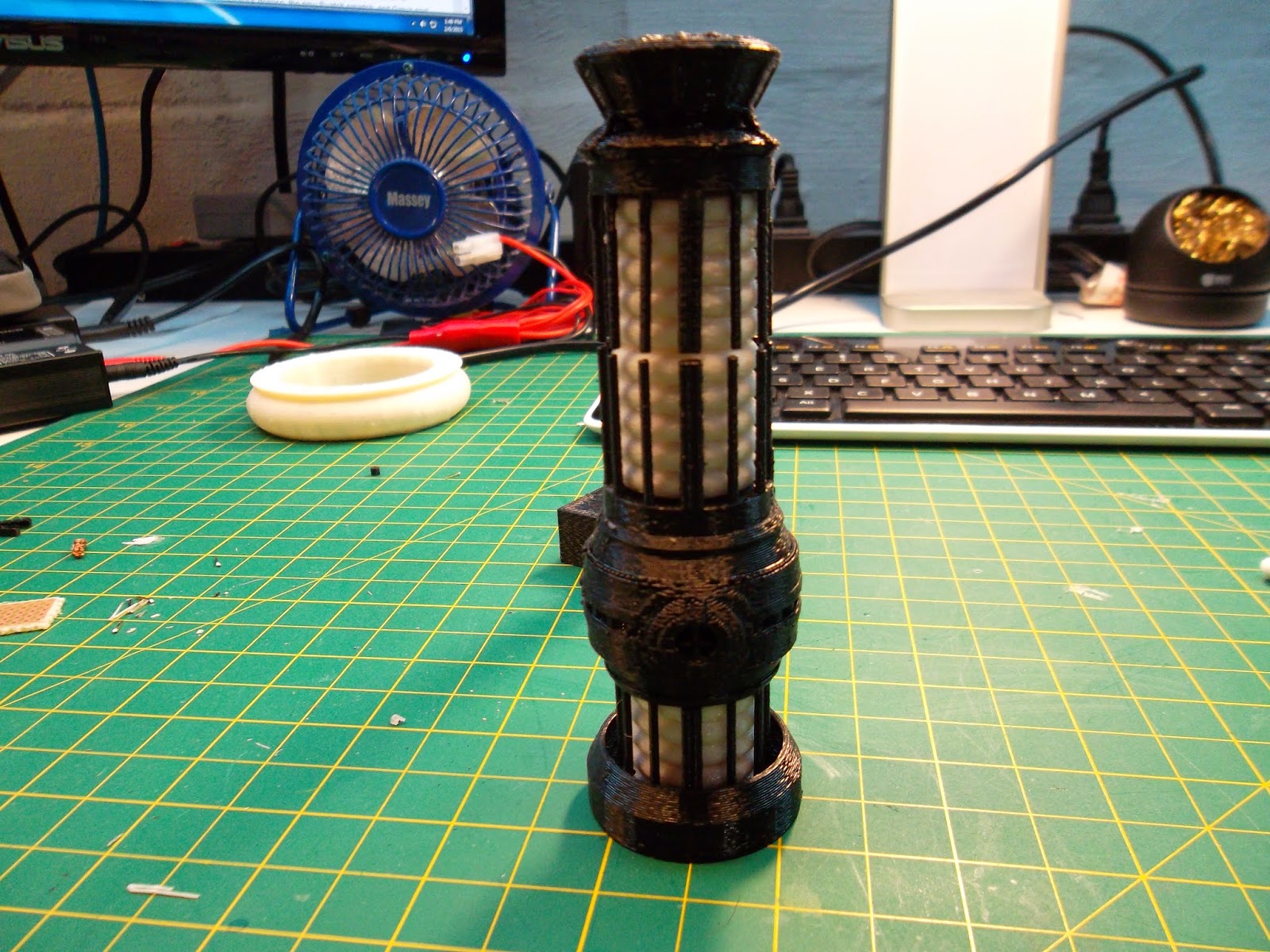
3D Printed Mini Tabletop Warp Core
3D Printed Mini Star Trek the Next Generation Warp Core with Neopixles
Background:
I first found a model of the Star Trek Next Generation warp core on Thingiverse about a year ago. The designer made it large enough to be about the size of a table lamp. I ,of course, wanted one instantly, however, I was a little wary of the print time all of the pieces required. At the time, my Solidoodle 2 wasn't the most reliable machine for prints longer than an hour or two. The largest part on this model would take about 12 hours to print, which meant overnight, and me not being able to keep an eye on it.
One year and several modifications to the 3D printer later, this project seems incredibly doable. At the same time, I needed to come up with some Christmas presents for my geeky friends and brother. Christmas was just a few weeks away and I did not have the time to print 3 "full size" warp cores, and construct them. At 25% scale however, I could do that.
Here is a video of the warp core completed, so you can know what you are getting into.
Here is the link for the video external to this page:
https://www.youtube.com/watch?v=Pi0VYY_Y1bo&feature=youtu.be
Construction:
All but one of the files needed are on the thingiverse page here: Thingiverse: Tabletop warp core
All the parts are printed at 25% normal size, .3mm layer height, and 40% fill.
(They could probably be at a lower percentage fill, but this is just what I had my slicer set at.)
(All credit for the Warp Core 3D design needs to go to ThePlanetMike. His work on the 3D model is awesome.)
I also needed to design a platform of sorts for the warp core to sit on, but to also hold the Adafruit Trinket that drives the neopixel strip. Here is a link to that file on Thingiverse: 25% warp core base
http://www.thingiverse.com/thing:666957
The side opening for the USB port was designed to fit the mini USB male connector on a cable I bought from Amazon. It should be big enough to fit most USB mini connectors, but if not, it can be widened with an exact-o knife.
I left out the three white pieces that are in the center of the "Warp Core MARC4.stl" file. At that scale they were just too frustrating and brittle for me to mess with at the time. This ended up making a pretty cool light effect that can be seen later on.
Electronics:
I used the 5V version of the trinket sold by Adafruit right here: 5V Adafruit Trinket
Solder the header pins that come with the trinket to the board.


The underside of the board is going to be facing inward on the base. That is, towards the warp-core. Orienting it this way gives easy access to the reset button so the board can be reprogramed if you want to change the light effects. To fit in the base, and allow the USB plug to fit, the entire assembly needs to be pretty thin. To achieve this I used a piece of proto-board with copper traces cut to fit on the trinket.


To make this work, some of the traces need to be cut with an Exact-o or equivalent. In the code that I provide, Pin 2 is used as the data pin. If you decide to use a different pin, obviously, you need to cut the traces in the way that works for your design.
IMPORTANT! Remove the black pin spacers from the header pins after you have soldered the pins in place. This lets the proto-board sit flush with the Trinket board.
Trim the extra pin length that sticks over the proto-board as low as possible without compromising the solder joint. I saved these trimmed pieces to use to bridge the solder pads together!
 |
| How to orient the board and where to cut traces |
 |
| Using the extra pin length to connect the Trinket pins to the copper traces |
The 5V line, Pin 2 for data and then the ground pin on the opposite side.
The neopixel strips can be bought here: Adafruit Neopixel Strip X8
I used another set of 4 header pins to connect the two strips.
Even up the header spacer so there is approximately an even amount of pins on either side of the spacer. Then solder to the DOUT side of one of the strips. It is important to mate up the DOUT of one strip to the DIN of the other strip. Otherwise...it just won't work.


Then, solder the other side of the header to the DIN side of the other strip of LED's.

Sorry, some of these pictures didn't come out perfectly. I think the idea gets across though.


Before you reinforce the joint with hot glue, this is a good point to program the board and make sure that everything is working. Just be gentle with the assembly.
The code is simple, and is easily modified to do different patterns and colors, please, feel free to do so. To program the trinket you need to use a special configuration of the Arduino IDE that is provided on the Adafruit site. Once you have that downloaded, it programs just like any other Arduino. There are countless tutorials on the inter-webs about this so I won't repeat it here.
IMPORTANT! The 5V pin of the Trinket is only capable of supplying 150mA of current, for the code below, that is just fine. If you modify the code and turn on more LED's at once (including multiple colors on the same die) it might cause a brownout.
Here is the code that I used:
// NeoPixel Ring simple sketch (c) 2013 Shae Erisson
// released under the GPLv3 license to match the rest of the AdaFruit NeoPixel library
#include <Adafruit_NeoPixel.h>
// Which pin on the Arduino is connected to the NeoPixels?
#define PIN 2
// How many NeoPixels are attached to the Arduino?
#define NUMPIXELS 16
// When we setup the NeoPixel library, we tell it how many pixels, and which pin to use to send signals.
// Note that for older NeoPixel strips you might need to change the third parameter--see the strandtest
// example for more information on possible values.
Adafruit_NeoPixel pixels = Adafruit_NeoPixel(NUMPIXELS, PIN, NEO_GRB + NEO_KHZ800);
int delayval = 250; // delay for half a second
void setup() {
pixels.begin(); // This initializes the NeoPixel library.
}
void loop() {
// For a set of NeoPixels the first NeoPixel is 0, second is 1, all the way up to the count of pixels minus one.
while(1){
for(int i = NUMPIXELS - 1; i >= (NUMPIXELS/2); i--) {
// pixels.Color takes RGB values, from 0,0,0 up to 255,255,255
pixels.setPixelColor(i, pixels.Color(0,0,255)); // Blue Bright
pixels.setPixelColor(i+2, pixels.Color(0,0,40)); // Blue Not So Bright
pixels.setPixelColor((NUMPIXELS-1)-i, pixels.Color(0,0,255)); // Blue Bright
pixels.setPixelColor((NUMPIXELS-3)-i, pixels.Color(0,0,40)); // Blue Not So Bright
pixels.show(); // This sends the updated pixel color to the hardware.
delay(delayval); // Delay for a period of time (in milliseconds).
pixels.setPixelColor(i, pixels.Color(0,0,0));
pixels.setPixelColor((NUMPIXELS-1)-i,pixels.Color(0,0,0)); // Setting the pixel to no output
pixels.setPixelColor((NUMPIXELS-3)-i,pixels.Color(0,0,0)); // Setting the pixel to no output
pixels.setPixelColor(i+2,pixels.Color(0,0,0));
pixels.show();
}
}
}
Just copy that code and flash it to the Trinket and you should have a blue strip that scans to the middle joint of the Neopixel strip. After that is working, reinforce the joint with hot glue.
 |
| Use hot glue to reinforce the joint |
 |
| Use hot glue to reinforce the joint |
Now, mount the electronics into the base. I like to plug in the USB cable and make sure the LED's are square from both the front and side and then hot glue the PCB into place.


All that is left is to assemble the warp core around the LED strips. I used super glue, but thin layers of hot glue would work as well.


If you look at the full scale version of the warp core, the middle most black support piece that holds the white light ring should probably be flipped. So its "base" is above the vertical pillars. Doing that makes the whole thing look a little better, but its a minor detail.
These made great gifts and everyone who got one loved it!
Thursday, November 20, 2014
Wow...three posts. This blog is on fire.
There are currently about 1000 projects going on inside my head, 20 of those have some kind of physical existence. The largest of the moment are the home theater and mame cabinet. Oh btw, if I didn't say in the exorbitant amount of posts below, my wife and I own a house now and have been building a home theater.
It has slowly been improving, from a new 1080p 3d capable 3000 lumen viewsonic projector a little over a year ago to the new reclining leather couches showing up in two days. The screen is getting worn. It used to be my portable projector setup screen, Velcro on the sides, folded and unfolded several times, stains and scratches on the surface are things that bother me...but apparently nobody else. That happens often as I understand.
The best way for me to explain these projects is through video, I get tired of and probably am not the best at explaining everything with text to the point that I am satisfied with its explanation.
So to you, the random ass person who is reading this, thank you. Maybe if you come back in a few days there might be something somewhat worth your time.
Wishful thinking,
Alex
Saturday, July 27, 2013
As would make sense for this blog, as there is currently no content worth anything, this will be an update for future readers to get a feel as to where everything stands.
My fiance' and I are currently renting a house, with no good space for a proper work bench. This is the main reason for me not building/hacking anything for several several months. The second reason is that there are currently very few funds available for the materials required for many of the projects I have listed in the previous post. Not only are we getting married in September, we are buying a house together. Anyone who has bought a house knows that it tends to eat up a large portion of your spare money. It is a good thing in the end though.
This house has the perfect space for a workbench for me. It will become the place that I build, record, and post all of my projects. I will also have a proper garage that will let me use and store some bigger tools, allowing some of my projects to expand. This excites me.
I have started recording all of my idea's in one place, and I post and record any information I find there that might improve or help the project in some way.
It will most likely be a few months down the road, but my next post will hopefully be from the new house and from the new work space. This will also include pictures for a change.
Until next time
Alex
Subscribe to:
Posts (Atom)